Bendix Automatic
Lubrication, Assembly, and Service Instructions.
This information is from a 1960 Bendix service pamphlet. It is for the older "Red Band" hub. The later hubs are similar
except that they use brake shoes instead of discs.
How It Works
The Bendix AUTOMATIC Coaster Brake is a two-speed unit which changes gear ratio without the use of external cables and hand controls.
The driving gear ratio can be changed at any time the rider desires by rotating the pedals slightly in the braking direction.
The transmission consists of two driving screws; one inside the other. These screws are connected by a planetary gear train which causes
them to turn at different speeds, ( high speed and low speed ). Tapered driving clutches on these screws try to engage and drive the hub at
their respective speeds. The faster turning clutch, ( high speed ) will always drive the hub unless it is blocked out of engagement, at which time
the low speed clutch will engage the hub and drive it. When high speed driving takes place, the hub overruns the low speed clutch in much the same fashion
as the coasting cycle in a standard coaster brake.
A sequence device is utilized to provide gear changing. This device blocks the high speed driving clutch on alternate back-pedalling
applications allowing low speed driving to take place. The design of the Bendix AUTOMATIC Brake is such that the low speed clutch is the only
member which aplies the brake. Braking always takes place through the gears giving full-time " power braking ".
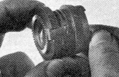
Disassembly Instructions
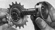
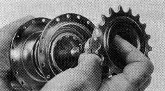
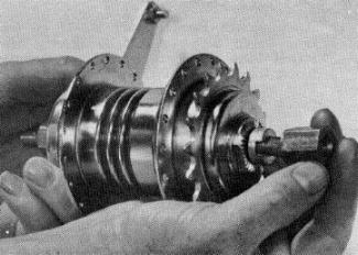 Remove the Adjusting Cone Lock Nut AB-35, using Wrench AB-102, shift brake to low gear, and rotate sprocket clockwise ( in the
driving direction ) until the sun gear is disengaged from planet gears. The cone can then be removed and the brake disassembled in the normal manner.
Remove the Adjusting Cone Lock Nut AB-35, using Wrench AB-102, shift brake to low gear, and rotate sprocket clockwise ( in the
driving direction ) until the sun gear is disengaged from planet gears. The cone can then be removed and the brake disassembled in the normal manner.
Lubrication
All internal parts should be covered with a liberal coating of grease. Particular attention should be paid to the bearings and to the axle
surface under the Low Speed Driving Screw. A liberal coating of grease on the axle and in the axle hole in the Low Speed Screw is necessary.
Assembly Instructions
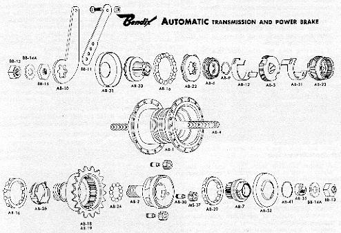
Assemble the parts in the following order:
Disc Assembly
1. Screw the Cone Arm and Disc Support AB-33, onto axle until 1 1/8" of axle projects beyond the outside end. ( Short spline end outside ).
2. Assemble hub retainer AB-16, ( large bearing ) on the anchor cone, (balls facing in ).
3. Install Anchor End Dust Cap AB-31; Brake Arm AB-10; and Lock Nut BB-15. Tighten lock nut ( 1" of axle should project outside of lock nut ).
4. Assemble Disc Set AB-22, by first placing a thin steel disc next to cone arm and disc support, alternate brass and steel disc are assembled
with the thick steel disc and inside end of the disc set. ( Disc Set is composed of six steel and five brass discs ). Steel discs should be lubricated
before assembly by dipping in grease to approximately one-third their diameter.
5. Install Plate Assembly AB-6, and lock the assembly with Retaining Ring AB-9.
6. Install the low speed clutch retarder spring in the groove of the plate assembly. ( Control Nut Retarders are the spring wires wrapped around
Plate Assembly AB-6 and High Speed Clutch Assembly AB-23--retarder springs are not sold seperately ). Assemble the Retarder Coupling, Low Speed
AB-12, on the Plate Assembly. ( This retarder coupling has no hooks ). When properly assembled the ends of the low speed clutch retarder spring will point toward the
open section of the Low Speed Retarder Coupling.
Clutch Assembly
7. Install the high speed retarder spring in the groove of the High Speed Clutch AB-23. ( High Speed Retarder Spring is not sold seperately and becomes part of
AB-23 assembly ). Assemble the High Speed Retarder Coupling AB-21, on this clutch. When properly assembled the ends of the high speed retarder spring will
point toward the open section of the High Speed Retarder Coupling.
8. Assemble the Low Speed Clutch AB-3, on the High Speed Retarder Coupling AB-21, by hooking one finger of the coupling through the slot in the
Low Speed Clutch and spreading the High Speed Retarder Coupling far enough to allow the opposite finger to through the other slot in the clutch. ( The
tapered surfaces on the clutches should slant in the same direction ). This comprises the Clutch Pack Assembly AB-45.
9. Install the Clutch Pack Assembly on the axle. Fingers on the Low Speed Retarder Coupling should project through the slots in the
Clutch Pack Assembly.
10. Align and center the lugs of the brass discs. Carefully align the slots in the hub with lugs on discs and assemble hub. If Disc Aligning Tool AB-103
is available it should be used to compress disc pack in order to hold the disc lugs in alignment before assembling hub.
Control Assembly
11. Assemble the Indexing Spring AB-26, over the indexing sleeve on the High Speed Screw Assembly AB-18 or 19. The three short lugs must
be next to the ball race shoulder.
Low Speed Screw Assembly
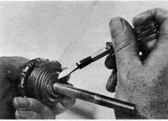
12. Assemble the Planet Gears MS-37, in the Low Speed Screw AB-2, by driving the Planet Pins AB-30, flush with, or slightly below the surface
containing the large holes. This now becomes the Low Speed Driving Screw Assembly AB-28.
Transmission Assembly
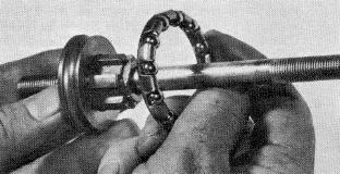
13. This is composed of the control assembly, the Low Speed Screw Assembly AB-28, and eleven loose 1/4" balls AB-24. The balls should
be placed in the internal ball race of the Control Assembly AB-18. The Low Speed Screw Asssembly AB-28, should bre assembled with AB-18,
and checked for free rolling.
14. Locate hub Retainer AB-16, ( large bearing ) in the drive end of the hub. Assemble transmission assembly by holding together and screwing clockwise
until both members are seated on their bearings.
15. Drop drive end Retainer AB-20, in place.
Dust Cap, Sun Gear and Cone Assembly
16. Locate Drive End Dust Cap AB-32, on Adjusting Cone and Sun Gear AB-7, and assemble drive end Dust Cap Lock Ring AB-41. Be sure dust cap seats
flush all the way around.
Final Assembly
17. Screw the Dust Cap, Sun Gear and Cone Assembly on axle until the sun gear engages the planet gears. ( It may be necessary to rotate the sprocket slightly
in order to engage the gears ). Use wrench BB-100, and backoff 90* - 120* ( degrees ). Hold cone in this position and tighten Lock Nut AB-35,
using Cone Adjusting Wrench AB-102.
 Trouble Shooting The Bendix Automatic
Back To Bunch "O" Bikes
Questions? Suggestions? Send an email
This Page Copyright (©) 2002